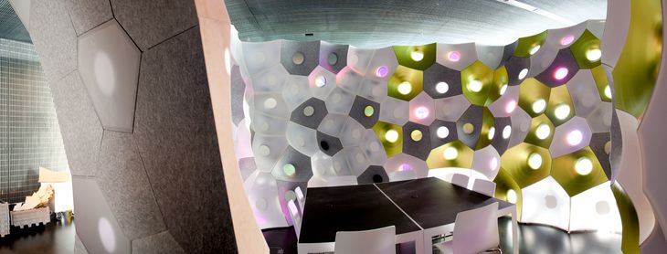
Cite as: Davis, Daniel. 2013. “Modelled on Software Engineering: Flexible Parametric Models in the Practice of Architecture.” PhD dissertation, RMIT University.
7.0 – Case C: Interactive Programming
Location: SmartGeometry 2011, Copenhagen, Denmark.
Project participants: Mark Burry, Jane Burry, John Klein, Alexander Peña de Leon, Daniel Davis, Brady Peters, Phil Ayres, Tobias Olesen.
Second iteration: The FabPod.
Location: RMIT University, Melbourne, Australia.
Project participants: Nick Williams, John Cherrey, Jane Burry, Brady Peters, Daniel Davis, Alexander Peña de Leon, Mark Burry, Nathan Crowe, Dharman Gersch, Arif Mohktar, Costas Georges, Andim Taip, Marina Savochina.
Code available at: yeti3d.com (GNU General Public Licence)
Related publications:Davis, Burry, and Burry, 2012.
Burry et al. 2011.
7.1 – Introduction

Figure 57: John Klein (left) and Alexander Peña de Leon (right) in a Copenhagen hotel at 3 a.m. writing code six hours before the start of SmartGeometry 2011.
To be writing code in Copenhagen at 3 a.m. was not an unusual occurrence. We had spent the past week in Copenhagen sleeping only a couple of hours each night as we rushed to get ready for SmartGeometry 2011. It turns out casting plaster hyperboloids is hard, much harder than the model makers from Sagrada Família make it look. And it turns out joining hyperboloids is hard, much harder than Gaudí makes it seem.1 When figure 57 was taken, we were just six hours away from the start of SmartGeometry 2011, and we were all exhausted from days spent fighting with the geometry and each other. So naturally, rather than verify the plaster hyperboloids joined as expected, we went to sleep for a couple of hours.
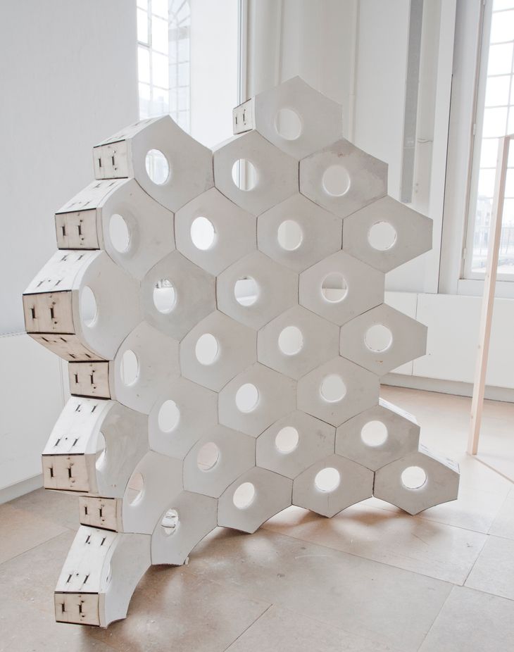
Figure 58: The responsive acoustic surface installed at SmartGeometry 2011. Slight gaps are still visible in the top- and bottom-most rows.
Sleeping is a decision we would come to regret two days later. The workshop was half way through and we had cut the formwork for roughly forty hexagonal plaster hyperboloid bricks, when we realised none of the hyperboloids joined together. Instead of sitting flush against one another, the brick’s wooden sides were angled such that they could only join together if there were slight gaps between the bricks. The error was small (less than 5mm on a brick 450mm wide) but these small errors accumulated through the stacking of the bricks, which caused visible gaps in the upper courses and prevented the topmost courses coming together at all (fig. 58). Without the time to recut the formwork, that single small error threatened the whole viability of the project. Once again we were without sleep. Thankfully the timber formwork had enough pliability to accommodate the error, although if you look closely at figure 59 you can see the timber is under such tension the whole wall bows slightly backwards.
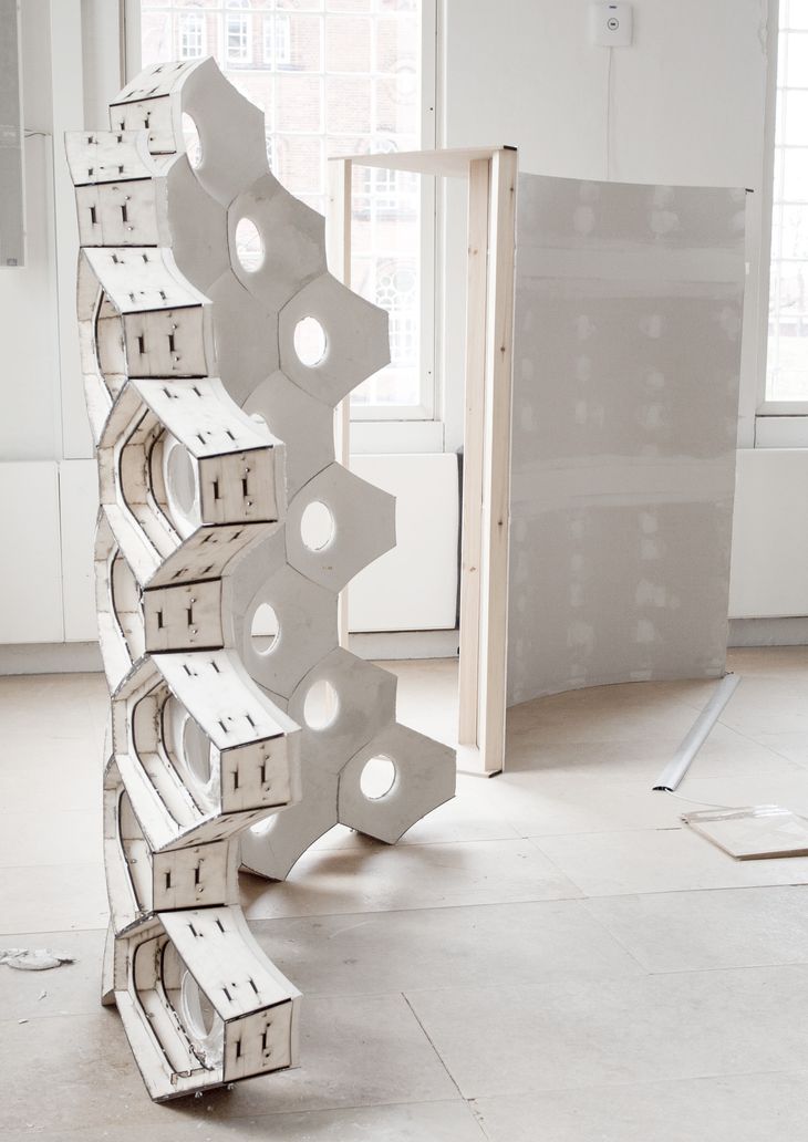
Figure 59: The responsive acoustic surface (foreground) with its counterpart, the flat benchmark surface in the background. The top of the responsive acoustic surface curves slightly backwards due to a small error in the shape of the brick. Bolts between the plywood frames help to pull the bricks together but also put the frame under a lot of stress.
This single small error can be attributed to exhaustion: in our fatigued state we did not verify that the code’s math generated the expected intersections between hyperboloids. This could be seen as a failing of our project management skills – a failure to allocate sufficient time to verify the code’s outputs. But it could also be seen as a failing of the coding environment – a failure to provide immediate feedback about what the math in the code was producing. The notion that programming environments fail to provide designers with immediate feedback forms the foundation of Bret Victor’s (2012) manifesto, Inventing on Principle. Victor, a user experience designer best known for creating the initial interface of Apple’s iPad, describes how the interface to most programming environments leaves the designer estranged from what they are creating:
Here’s how coding works: you type a bunch of code into a text editor, kind of imagining in your head what each line of code is going to do. And then you compile and run, and something comes out… But if there’s anything wrong, or if I have further ideas, I have to go back to the code. I go edit the code, compile and run, see what it looks like. Anything wrong, go back to the code. Most of my time is spent working in the code, working in a text editor blindly, without an immediate connection to what I’m actually trying to make.
Victor 2012, 2:30
In this case study I follow a similar line of thinking, observing that typically for architects there is a significant delay between editing code and then, much later, realising your plaster hyperboloids do not fit together as expected. As such, I use this case study to consider how coding environments could provide architects with more immediate feedback about what their code produces. I begin by discussing the history of interactive programming and the lack of interactive programming environments for architects. I then describe an interactive programming environment I created, dubbed Yeti, and compare Yeti’s performance to two existing coding methods on three architecture projects (including revisiting the plaster hyperboloids of the Responsive Acoustic Surface). But first I want to return to Bret Victor’s manifesto.
7.2 – The Normative Programming Process
![Figure 60: The Edit-Compile-Run loop for a Rhino Python script. A designer must go through this loop every time they want to see what their code produces. In the best case it takes a couple of seconds to move between writing code [1] and seeing the output [6] but this period can be much longer if the script is computationally intensive to run.](/img/edit-compile-run-loop-hBOf7Cep9F-730w.jpeg)
Figure 60: The Edit-Compile-Run loop for a Rhino Python script. A designer must go through this loop every time they want to see what their code produces. In the best case it takes a couple of seconds to move between writing code [1] and seeing the output [6] but this period can be much longer if the script is computationally intensive to run.
In Inventing on Principle, Bret Victor (2012, 2:30) describes the normative programming process as, “edit the code, compile and run, see what it looks like.” This sequence of events is commonly known as the Edit-Compile-Run loop. In the loop (fig. 60), the programmer edits the text of the code [1], presses a button to activate the code [2], and then waits. They wait first for the computer to validate the code [3], then they wait for the computer to compile the code into machine-readable instructions [4], and finally they wait for the computer to run this set of instructions [5]. Only then can the programmer see what their code produces [6]. Victor (2012, 18:00) says that good programmers shortcut this process by mentally simulating the running of code – a somewhat perverse situation considering they are more often than not sitting in front of a machine dedicated to doing just that.
For architects, the delayed feedback from the Edit-Compile-Run loop proves problematic. Ivan Sutherland (1963, 8) disparagingly called this “writing letters to rather than conferring with our computers.” Yet shortcutting this process using mental simulation, as good programmers often do, clashes with Nigel Cross’s (2011, 11) observation that “designing, it seems, is difficult to conduct by purely internal mental processes.” Cross’s contention that designers need to have continual feedback, separate from their internal monologue, is shared by Sutherland (1965), Victor (2012), and many others (Schön 1983; Lawson 2005; Brown 2009). This view is reinforced by design cognition research that shows any latency between a designer’s action and the computer’s reaction is problematic for architects since delays exacerbate change blindness, which makes it hard for designers to evaluate model changes (Erhan et al. 2009; Nasirova et al. 2011; see chap. 2.3). With designers potentially blind to the changes they make, Rick Smith (2007, 2) warns that a change to a parametric model “may not be detected until much later in the design phase, or even worse, in the more expensive construction phase.” Smith’s warning rings true with the hyperboloid bricks of the Responsive Acoustic Surface, where feedback from a coding error was not apparent until the bricks were stacked during the construction phase.
The Edit-Compile-Run loop prevails, argues Victor (2012, 28:00), because most programming languages “were designed for punchcards” where “you’d type your program on a stack of cards, and hand them to the computer operator, and you would come back later” – an “assumption that is baked into our notions of what programming is.” While punchcards may explain the origins of the Edit-Compile-Run loop in programming, there have been many developments in programming since the days of punchcards. In particular, significant developments have been made to the tools programmers use to write code, known as Integrated Development Environments (IDEs). Modern IDEs often augment the Edit-Compile-Run loop so programmers do not have to wait for feedback. For example, some IDEs identify simple logical errors before the code is run, and some IDEs suggest and explain programming commands while programmers are writing them (a feature known as autocompletion). Other IDEs allow the basic editing of running code, which enables programmers to make minor changes without cycling back through the edit-compile-run loop (this is known as interactive debugging). These types of IDE features makeup part of Section 2.3.1 of the Software Engineering Body of Knowledge Version 1.0 (Hilburn et al. 1999); a section of knowledge that often reinforces the notion that programming languages were designed for punchcards, while also offering ways of making Edit-Compile-Run loop more interactive.
The interactive feedback mechanisms of many modern IDEs have not filtered down to the environments architects write code in. Like professional programmers, architects use languages based on the Edit-Compile-Run loop, with Leitão, Santos, and Lopes (2012, 146) pointing out that even popular languages like “RhinoScript are a descendant of a long line of BASIC dialects that started much earlier, in 1964.” But unlike professional programmers, who have the advantages of cutting edge IDEs, Leitão, Santos, and Lopes (2012, 143) say that in the context of architecture “the absence of a (good) IDE requires users to either remember the functionality or read extensive documentation.” Thus architects are left to contend with the historic Edit-Compile-Run loop without many of the interactive conveniences present in the IDEs used by modern software engineers. This lack of interactivity in the programming process causes pronounced latency between the designer writing code and the computer generating the geometric results, which makes evaluating code changes potentially difficult for architects.
7.3 – The Interactive Programming Process
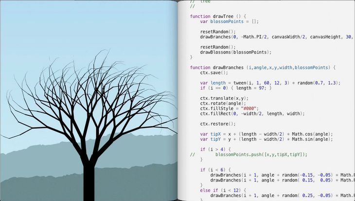
Figure 61: Bret Victor’s (2012) IDE from Inventing on Principle. Since the programming environment is interactive, the code and the image are always in sync. As shown in the three frames, changes to the code also immediately change the image produced by the code – without the designer manually activating the Edit-Compile-Run loop to see them.
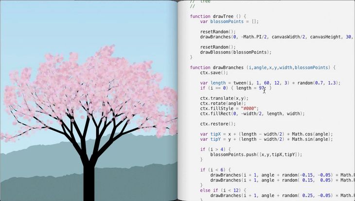
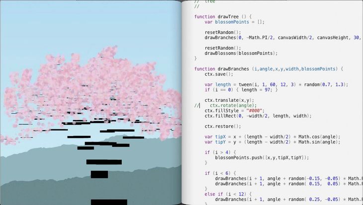
Interactive programming (also known as live programming) seeks to remove any latency between writing and running code. Instead of a programmer activating the Edit-Compile-Run loop every time they want to see what their code produces, a programmer using interactive programming directly changes the code of an already running program.2 Bret Victor (2012) demonstrates interactive programming with a programming environment he created for drawing and animating two-dimensional objects (fig. 61). When Victor changes code in the text editor, the corresponding image produced by the code changes instantly – without Victor manually pressing a button to execute the Edit-Compile-Run loop. With the code always in sync with the image it produces, Victor (2012, 2:00) argues that his environment gives designers “an immediate connection to what they are creating.”
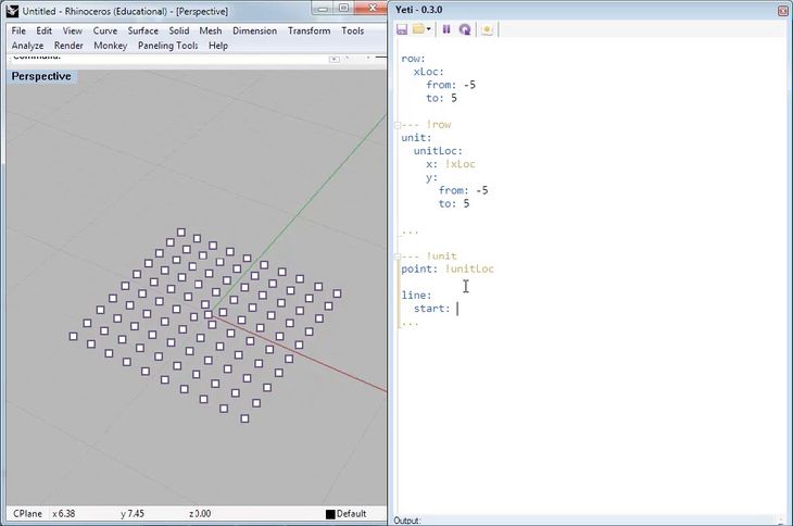
Figure 62: Yeti, an interactive programming plugin for Rhino. Like with Victor’s IDE (fig. 61), the code and the model are always in sync. Whenever the code changes, the model produced by the code automatically changes as well.
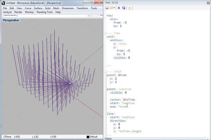
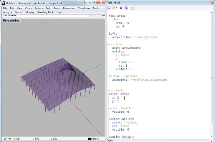
To assist architects creating parametric models I developed an interactive programming environment named Yeti (fig. 62). On first glance Yeti looks similar to Victor’s interactive programming environment, however, there are a number of key differences between the two IDEs. The most obvious difference is that Victor’s environment focuses on the real-time drawing of two-dimensional objects, while Yeti supports the real-time remodelling of three-dimensional objects (since three-dimensional objects generally require more computational resources, making the calculations in real time is significantly more challenging than with two-dimensional objects). The second significant difference is that Victor’s presentation of his environment in January 2012 comes a number of months after I first presented Yeti, and released Yeti’s source code, in May 2011. While Victor was not the first to create an interactive programming environment, I have chosen to cite him both because he clearly articulates the problems with the normative programming process, and because his legacy of creating interfaces for Apple adds credibility to the argument that interactive environments, like Yeti, are important emerging areas of research for designers.
While Yeti predates Victor’s programming environment by a couple of months, a number of other interactive programming environments predate both of them by many years. The origins of interactive programming date back to the programming languages LISP (first version: 1958) and SmallTalk (first version: 1971), both of which allow programmers to modify code while it runs. The initial emphasis was on updating software without needing to shut down running programs (useful for critical systems). These techniques were extended, in particular by musicians, to allow the real-time modification of code. For musicians, these interactive programming environments enable them to modify code driving musical compositions whilst immediately experiencing the modification’s sonic implications. The first performance with an interactive environment was by Ron Kuivila at STEIM in 1985 using the FORTH programming language (Sorensen 2005). In the early 1990s, interactive textual programming environments gave way to interactive visual programming environments like Max/MSP (the precursors of the visual programming environments architects use today). While visual programming remains popular with musicians, a number of new interactive textual programming languages have emerged, including the Smalltalk based Supercollider (McCartney 2002) as well as the LISP based ClunK (Wang and Cook 2004) and Impromptu (Sorensen 2005). Outside the domain of music there is a scattering of interactive programming environments aimed at designers, such as SimpleLiveCoding for Processing and the widely used Firebug for CSS editing. While real-time interactive programming suits these creative contexts, the computational stress of three-dimensional design has meant that architects – prior to my research – have been unable to utilise interactive programming.
The crux of all interactive programming environments is removing the latency between writing and running code. Existing interactive programming environments achieve this in a number of ways:
- Automation Rather than waiting for the user to manually tell the Edit-Compile-Run loop to execute, the loop can be set to run automatically and display the results whenever the code is changed – as is done in SimpleLiveCoding (Jenett 2012). This is a bit like stop-motion animation; the user sees a single program adapting to code changes but really they are seeing a series of discrete programs one after the other (like frames in a movie). In order for this animation to feel responsive, the elapsed time between the user changing code and the completion of the Edit-Compile-Run loop should ideally be a tenth of a second and certainly not much more than one second (Miller 1968, 271; Card, Robertson, and Mackinlay 1991, 185). For simple calculations these time restrictions are manageable. However, for complicated calculations it becomes impractical to recompile and recalculate the entire project every time the code changes, especially if the change only impacts a small and discrete part of the finished product.
- Sequencing For musicians using interactive programming, changes must happen relative to an underlying time signature. Code from Supercollider (McCartney 2002), ClunK (Wang and Cook 2004), and Impromptu (Sorensen 2005) all generate timed sequences of actions for the computer to perform. As the code changes, new actions are automatically queued into the sequence while old actions are seamlessly discontinued (Sorensen 2005), which avoids the stopping and restarting necessary when using the Edit-Compile-Run loop. This method has been adapted to generate simple geometry in time to music (Sorensen and Gardner 2010, 832). However, for architects doing computationally demanding geometric calculations, generating geometry rhythmically is not as important as generating geometry quickly. For this reason, sequencing is unsuitable in an architectural context.
- Hot-Swapping The Edit-Compile-Run loop recompiles every line of code even if some lines have not changed since the last time the loop was activated. Instead of compiling every line of code, hot-swapping allows small chunks of code to be independently compiled and then integrated with the unchanged parts of the program – while the overall program continues to run. This reduces the latency of compilation but does not reduce the latency of running the code.3 Since geometric calculations take orders of magnitude longer than the compilation of code, the savings from hot-swapping in an architectural context are likely comparable to those of automation.
Although there are a range methods for reducing the latency between writing and running code, none of the existing methods are suited to the unique challenges of performing geometric calculations in real time. These are challenges not present in other design disciplines currently using interactive programming (such as web-design, musical performance, and two-dimensional animation). Despite the range of textual interactive programming environments available to other designers, architects currently have no option but to contend with the separation induced by the Edit-Compile-Run loop.
7.4 – Interactive Visual Programming
While none of the existing interactive textual programming environments are particularly suited to architects, many non-textual programming environments allow the interactive creation of geometry. Grasshopper, Houdini, and GenerativeComponents all overcome the problem of performing geometric calculations in real time by representing geometric relationships with a Directed Acyclic Graph (DAG) (Woodbury 2010, 11-22). As explained in chapter 5.3, a DAG is a type of flow-chart where nodes represent geometric operations and directed edges represent the flow of data between pairs of nodes. When a node is changed, the model is updated by propagating the changes along the directed edges to update the affected nodes. This minimises the calculations involved in updating the model since the only nodes recalculated are those affected by the change. Rather than recalculating every geometric operation, as with the Edit-Compile-Run loop, the selective updating of a DAG saves unnecessary geometric calculations, greatly compressing the time between writing and running code.
While visual programming enables architects to work interactively, there are still limitations when compared to textual programming. In the previous chapter (chap. 6) I demonstrated that visual programming environments do not support structure as elegantly as many textual programming environments do. Partly citing my research from the previous chapter, Leitão, Santos, and Lopes (2012, 160) conclude, “learning a textual programming language takes more time and effort than learning a visual programming language, but this effort is quickly recovered when the complexity of the problems becomes sufficiently large.” I suspect visual programming is easier to learn partly because the interactivity of visual programming provides the continuous feedback Green and Petre (1996, 8) say novice programmers require. While interactive visual programming languages are successful in the domain of architecture, there remains an opportunity to create an interactive textual programming language that combines the structural benefits of textual programming with the ease of use brought about by the interactivity of visual programming.
7.5 – Introducing Yeti
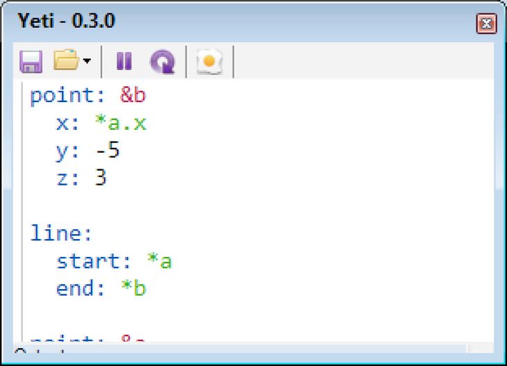
Figure 63: The Yeti interface. The primary element is a textbox for writing code. The code within the textbox is automatically coloured: numbers (black), geometry (blue), names (red), references to named geometry (green). Above the textbox are a row of icons, from left to right: save, open, pause interactive updating, force update, and bake geometry (export to Rhino). The geometry created by the code is displayed in another window (not shown).
Yeti is an interactive textual programming environment I developed to support the creation of three-dimensional geometry. At first glance Yeti looks much like any other textual programming environment, a large textbox for writing code is positioned underneath a horizontal menu of icons (fig. 63). The icons give the only outward hint of Yeti’s interactive behaviour: instead of an icon for running the code there is an icon for pausing Yeti’s continuous evaluation of the code. Beyond these icons the difference between Yeti and other IDEs only really becomes apparent when the designer begins writing code. Rather than writing a block of code and then pressing the run icon to see geometry generated by the code (through the Edit-Compile-Run loop), designers writing code in Yeti always see what their code generates. The geometry is in sync with the code that produces it, so every time the code changes the geometry automatically changes as well.
In order to perform geometric calculations fast enough that they feel interactive, Yeti employs a DAG to coordinate recalculating the geometry. This is essentially the same concept powering the interactivity of the visual programming environments Grasshopper, Houdini, and GenerativeComponents. However, Yeti’s DAG is not generated through a visual interface, rather it is defined textually through the relational data format YAML.
The YAML Language
YAML’s inventor, Clark Evans (2011), describes YAML as a “human friendly data serialization standard.” While YAML is technically a data format, Yeti uses it like a dataflow programming language to describe the structure of a DAG.4 As such, Yeti’s code is paradigmatically distinct from the procedural programming languages that underlie most other textual programming environments used by architects (see chap. 5.2). Yeti may therefore seem initially unfamiliar to designers versed in procedural programming. However, YAML’s relatively minimal syntax is fairly easy to pickup.
YAML comprises primarily of key:value pairs. The key is always assigned the value following the colon. For example, the code to assign a variable the value of 10 is:
variable:10
More complicated values are assigned through a list of key:value pairs that are separated from the parent key with indentation. For example, a point at the coordinate (-10,10,13) can be written as:
point:
  x: -10
  y: 10
  z: 13
These key:value pairs map directly into a DAG. Every key represents a node in the graph, while values express either a property of the node, or a relationship to another node. For example:

Relationships between geometry can be established by labelling keys with names beginning with an ampersand [&] and then referencing their names later (references begin with an asterisk [*]). For example, the following code creates a point named basePoint and generates a line extending vertically from basePoint:

Yeti extends the YAML language so that designers can define new keys. To create a key, a designer must first create a prototype object for the key. The prototype object begins with the YAML document marker [---] immediately followed by the name of the object (names start with an exclamation mark [!]). Under this header, the designer defines the geometry of the prototype object. Any geometry given a name starting with an exclamation mark [!] becomes a parameter of the object that can be specified when the object is instantiated. The end of the object is delimitated by the YAML document marker […]. For example, the code from the preceding example can be turned into an object named column and then used to generate two columns starting at (20,10,0) and (2,30,0), like so:
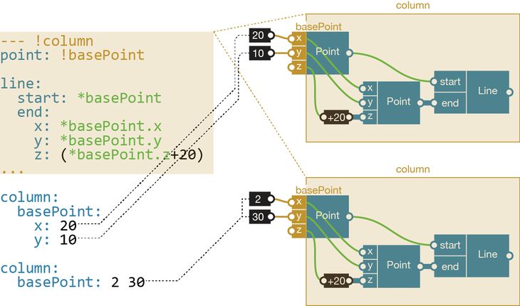
The user defined keys help structure the Yeti code. Like a module they encapsulate code with defined inputs and outputs (denoted by the exclamation mark [!]). However, they go further than the modules discussed in chapter 6 by providing more object-oriented features like instantiation (the creation of multiple instances that draw upon the same prototype) and inheritance (one user defined key can be based on another user defined key). In essence, YAML allows Yeti to mix the structure of textual languages with the performative benefits of directed acyclic graphs.
The Yeti Development Environment
There are a number of other interactive features in the Yeti development environment. Many of these are commonly part of the IDEs software engineers use but, according to Leitão, Santos, and Lopes (2012, 143), they are seldom a part of the IDEs architects use. The following describes some of Yeti’s main interactive features.
Autocompletion:
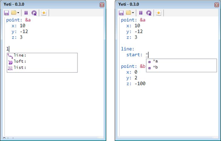
Figure 64: Yeti offering autocomplete suggestions as the designer types. Left: After the designer types the letter L, Yeti lists all the keys that start with the letter L. When the designer selects a key, Yeti will then suggest parameters for that key. Right: The designer begins typing a reference and Yeti produces a list of names used in the code.
As a designer types, Yeti predicts what the designer is typing and suggests contextually relevant keys, names, and objects. This saves the designer from looking up keys and parameters in external documentation.
Robust Error Handling:
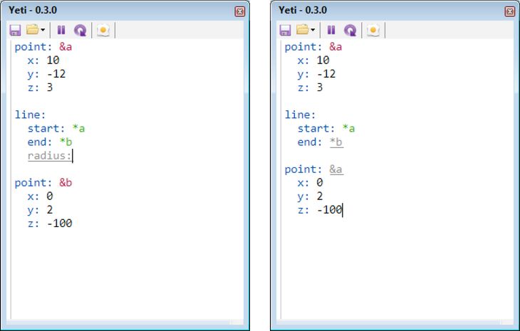
Figure 65: Errors in Yeti are coloured grey and underlined. In both of these examples, Yeti continues to function even though there are errors in the code. Left: Radius is not a valid parameter for a line, so it is marked as an error. Right: Since there is no key named &b, the pointer *b is marked as an error; and because there are two keys named &a, the second one is highlighted as an error.
Yeti highlights errors as they are written (common errors include spelling mistakes, syntax errors, and duplicate names). Errors generally cause procedural languages to stop running because there is no clear way to progress past an error in a sequence of instructions. Since Yeti does not use a sequence of instructions but rather a dataflow language, Yeti can continue to run code that contains errors by only parsing the error-free portions of the code into a DAG. This is important in an interactive context since evaluating code while it is being written often requires evaluating incomplete code that contains errors.
Code Folding:
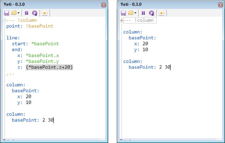
Figure 66: Left: The column object’s code expanded. Right: The column object’s code collapsed (the code is hidden but still functioning).
The code for a prototype object can fold into a single line, effectively hiding it. These folds allow the user to improve juxtaposability by hiding irrelevant parts of the code while exposing the parts currently important.
Interactive Debugging:
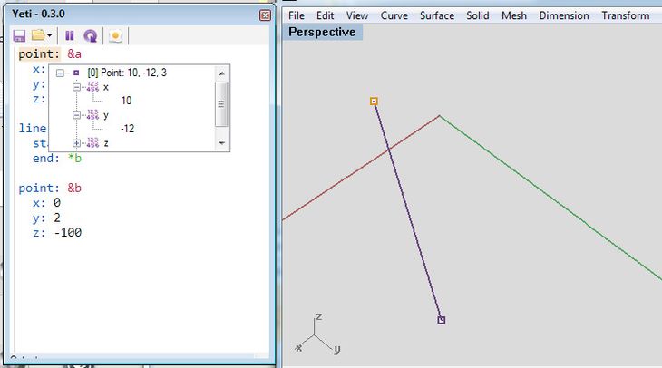
Figure 67: Clicking on the word point: in the code produces a window allowing the designer to inspect all the properties and parameters of the point. At the same time, the selected code and the corresponding geometry are highlighted in orange.
To help clarify the often-enigmatic connection between code and geometry, clicking on any key in Yeti highlights the geometry controlled by that key. A parameter window is also generated so that the user can drill down and inspect all the properties driving the geometry. Similarly, clicking on any referenced name highlights where the reference comes from in the code and the geometry it refers to. Yeti is able to provide all this information since the keys in the YAML code are directly associated with parts of the model’s geometry via nodes in the DAG.
The impediments to generating geometry with interactive programming are overcome in Yeti by employing a DAG to manage geometric calculations. The DAG helps reduce the latency between writing code and seeing the geometry produced. Furthermore, the DAG also helps power other interactive features like robust error handling and interactive debugging. In the following pages I consider how these features perform when used on three design projects, and I compare this performance to that of other programming environments available to architects.
7.6 – Benchmarking Yeti

Figure 68: The three benchmark projects in Yeti. Left to right: Kilian’s first roof, Kilian’s second roof, and the hyperboloids from the Responsive Acoustic Surface.
Method
To test the viability of generating parametric models with interactive programming, I carried out three design tasks using Yeti (fig. 68). It was not clear whether interactive textual programming would cope with creating a parametric model, let alone creating one in the midst of an architecture project. I therefore selected three design tasks that stressed a number of essential parametric techniques while letting me clearly isolate and observe the performance of interactive programming. The first two design tasks come from a pair of tutorials Axel Kilian developed in 2005. The tutorials teach designers to model a pair of parametric roofs and introduce “several key parametric modelling concepts” (Woodbury, Aish, and Kilian 2007, 226) such as arrays, constraints, and instantiation. Recreating the tutorials in Yeti ensures these key parametric modelling concepts are also possible with interactive programming. The third design task revisits the plaster hyperboloids of the Responsive Acoustic Surface. Given the computational challenges in calculating the intersections between hyperboloids, the project is an ideal setting for finding the limits of Yeti’s interactivity.
As a benchmark I repeated the three design tasks with two established methods of programming, both of which I am adept at: interactive visual programming in Grasshopper (version 0.8.0052), and textual programming with Rhino Python (in Rhino 5, version 2011-11-08). By repeating the design tasks I was able to compare Yeti’s performance to that of established programming methods through the metrics established in chapter 4. In particular I was interested in the following qualitative metrics:
- Functionality: Are all the modelling tasks able to be performed by every programming method?
- Correctness: Do programs do what is expected?
- Ease of use: Are the modelling interfaces easy to use?
I was also interested in the following quantitative metrics from chapter 4.3:
- Construction time: How long did the respective models take to build?
- Lines of Code: How verbose were the various programming methods?
- Latency: How quickly did code changes become geometry?
The intention is not to definitively say one programming method is better than the other, rather the intention is to capture the primary differences between these programming methods while verifying that Yeti can complete the same key design tasks. Recent studies employing a similar method include: Janssen and Chen’s (2011) comparison of the visual programming environments Grasshopper, GenerativeComponents, and Houdini; Leitão, Santos, and Lopes’s (2012) comparison of Grasshopper and the textual language Rosetta; and Celani and Vaz’s (2012) comparison of Grasshopper and the textual language Visual Basic. The first hand accounts in these studies are largely successful at establishing the primary differences between the programming methods they compare, differences I aim to establish in this case study of interactive textual programming.
Benchmark 1 and 2: Kilian Roofs
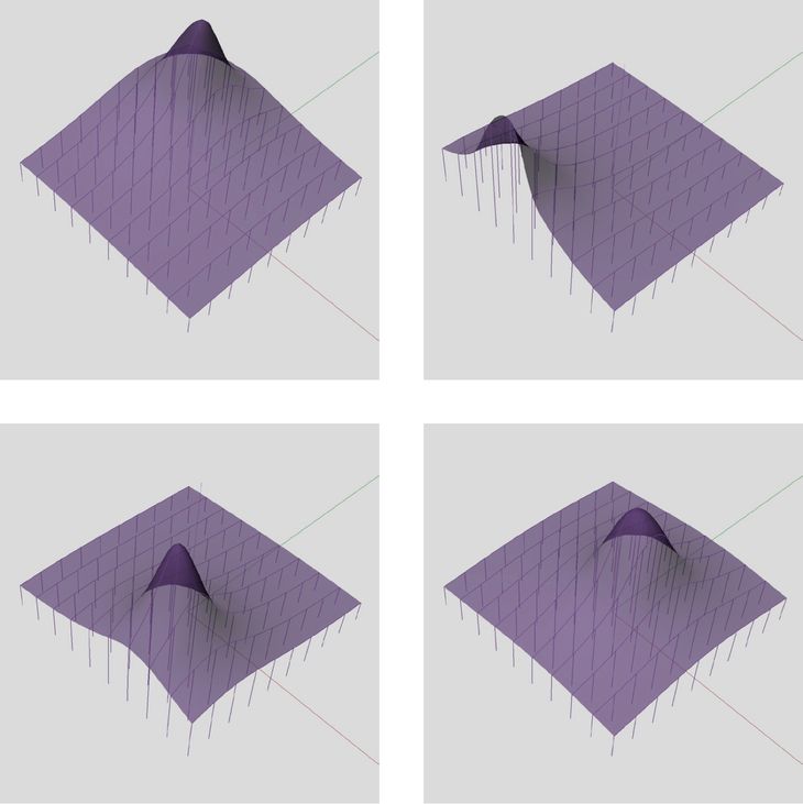
Figure 69: Four variations of Kilian’s first roof generated with Yeti. The roof rests on a grid of columns whose height varies to accommodate a tree under the roof. The height of any particular column is a function of the distance between the column and a point representing the tree. When the point moves, the roof readjusts to allow for the tree’s new location.
When Axel Kilian developed his pair of parametric modelling tutorials in 2005, neither Grasshopper nor Rhino Python had been invented and GenerativeComponents was still two years away from being commercially available.5 For architects who had never encountered parametric modelling, Kilian’s tutorials showcased “several key parametric modelling concepts and quickly yielded a form with some architectural credibility” (Woodbury, Aish, and Kilian 2007, 226). In particular, each tutorial teaches students how to model a roof that adapts to its context, while also introducing students to dataflows, arrays, b-splines, and the instantiation of objects that are topologically identical but physically different. To complete these tutorials in Grasshopper, Rhino Python, and Yeti, all the programming methods must be capable of performing the essential parametric modelling techniques outlined in Kilian’s tutorials.
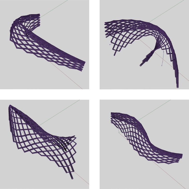
Figure 70: Four variations of Kilian’s second roof generated with Yeti. The roof is made an array of parabolas lofted together to make a surface that is then diagonally crisscrossed with tubes. The parabolas follow the path of a curve and if the curve is adjusted, the roof readjusts to follow the curve.
Functionality and Correctness
Both of Kilian’s roofs could be recreated in Grasshopper, Python, and Yeti. In this sense all the environments were correct: the code from every modelling environment correctly generated the expected geometry. There are however differences in functionality. Yeti has a limited geometric vocabulary in comparison to either Grasshopper or Python. While this was not a hindrance in creating the roof models, on other projects this may prevent Yeti from correctly generating the required geometry (at least until Yeti’s vocabulary is further developed). In this sense Grasshopper and Python are more functional than Yeti since they both offer what Meyer (1997, 12) calls, a far greater “extent of possibilities provided by a system.” Beyond the geometry of the various modelling environments, there are a number of key differences in functionality that I will expand upon shortly, including the management of lists, the baking of geometry, and the creation of custom objects.
Construction Time
The first roof (fig. 69) took me four minutes to build in Grasshopper, six minutes to build in Yeti and sixteen minutes to build in Python. I recorded myself building the Python model and in the video it is clear that the roof took a while to build because I spent a lot of time writing code to manage arrays and bake geometry. Since I had no feedback about whether my code worked, I then had to spend time testing the Python code by cycling through the Edit-Compile-Run loop. Both Grasshopper and Yeti have built-in support for simple arrays and geometry baking so I did not have to spend time creating them, which led to simpler models and a reduced construction time.
The second roof (fig. 70) is geometrically more complicated than the first. In Grasshopper the model took twenty-five minutes to build, involving many manipulations of the standard array to generate the diagonal pattern. These array manipulations were less of a problem in Yeti and Python since both environments allowed me to define a diagonal panel that could then be instantiated across a surface. Because of the way geometry is generated relative to axes in Yeti and Python, modelling the roof’s parabolic ribs and aligning them to the path was surprisingly difficult in both programming environments. In the end the model took forty minutes in Yeti and sixty-five minutes in Python.
Lines of Code
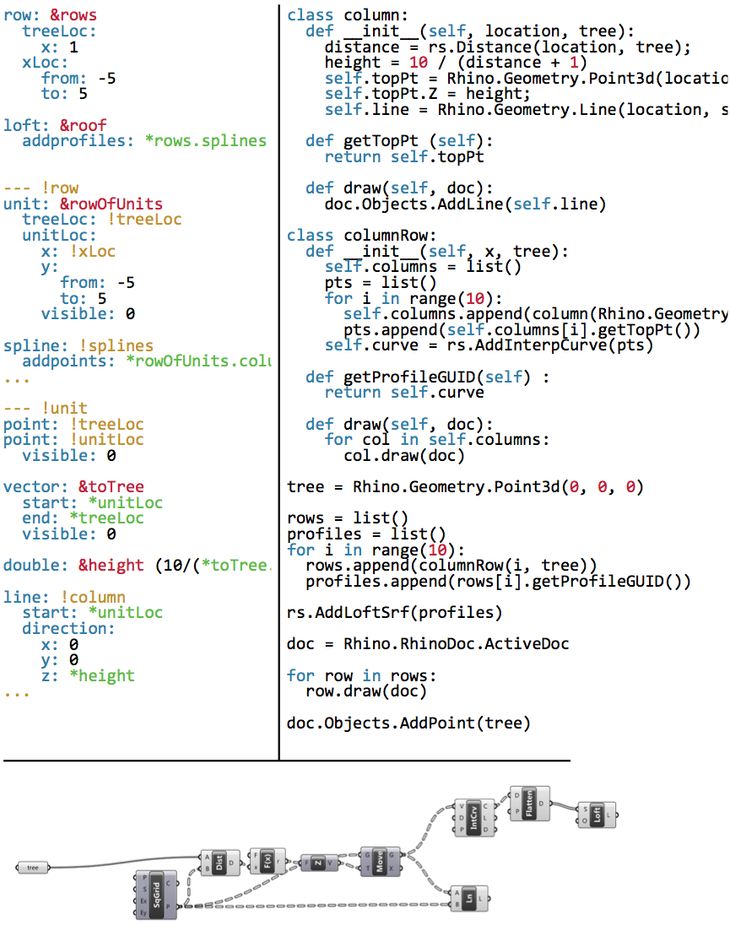
Figure 71: The roof from Kilian’s first tutorial in Yeti (left), Python (right), and Grasshopper (bottom). While the Yeti and Python code are of a similar length, the lines of code do not correspond due to the differences in programming paradigms. The Yeti code is also noticeably sparser than the Python code. But both the Python and Yeti code looks verbose when compared to the equivalent code in Grasshopper.
The Yeti scripts and the Python scripts were of a similar length (fig. 71); the first model required thirty-six lines of code in Yeti and thirty-five in Python, while the second model required ninety-three lines of code in Yeti and seventy-eight in Python. Although the programs have a similar number of lines, there are very few correlations between lines due to the differences between the two programming paradigms (Yeti being dataflow based and Python being object-oriented). The Yeti code is noticeably sparser than the Python code and contains on average just ten characters per line, whereas the Python code contains twenty-five characters per line. This is predominantly because Python is a general-purpose language, so differentiating commands generally requires more verbosity than in Yeti (for example, the point command in Python requires twenty-two characters [Rhino.Geometry.Point3d] whereas in Yeti it requires just six characters [point:]).

Figure 72: The roof from Kilian’s second tutorial in Grasshopper. The lack of structure in this model makes it difficult to understand the model’s fifty-two nodes.
The size of a visual program is not directly comparable to the size of a textual program but, having said that, the Grasshopper model for the first roof does look smaller and less complex than the corresponding textual programs (fig. 71). The Grasshopper model for the first roof contains just ten nodes and has a cyclomatic complexity of five, which means it is about half the size of the median Grasshopper model (see chap. 4.3). In comparison, the Grasshopper model for the second roof contains fifty-two nodes and has a cyclomatic complexity of twenty-four (fig. 72). The second model begins to exhibit some of the problems typical of larger unstructured visual programs that I discussed in chapter 6. In particular, it is almost impossible to infer the model’s function by just looking at the nodes, and even knowing the model’s function, it is difficult to do things like identify the nodes that generate the roof shape or understand why four nodes generate points just past midway in the model. While the code for the Yeti and Python models can also be hard to understand, the structure inherent to textual programs at least provides a few clues to aid reading the models.
Latency
Yeti remained interactive while designing both of the roofs. On the first roof, code changes took on average 50ms to manifest in changes to the geometry. On the second roof these changes took 27ms. Grasshopper was similarly responsive, implementing changes on the first model in 8ms and taking 78ms on the second model. All of these response times fall well inside Miller’s threshold of 100ms, which is the threshold for a system to feel immediately responsive (Miller 1968, 271; Card, Robertson, and Mackinlay 1991, 185). Python fell outside this threshold, taking 380ms to generate the first model and 180ms to generate the second. These times only measure the running time of the Python program and do not include the time the spent activating and waiting for the Edit-Compile-Run loop. When these other activities are taken into consideration, the Python code takes on average between one and two seconds to execute.
Ease of Use
Ease of use is hard to define since it depends on the “various levels of expertise of potential users” (Meyer 1997, 11). The Kilian models demonstrate that, at the very least, interactive textual programming in Yeti can match the functionality both of non-interactive textual programming in Python, and of interactive visual programming in Grasshopper. These functional similarities, combined with similarities in code length and slight improvements in construction time, indicate that interactive programming is a viable way to textually program parametric models. The reductions in latency are apparent when reviewing the videos of the various models being created. In the videos of Grasshopper and Yeti, the geometry is continuously present and changing in conjunction with the code. The distinction that often exists between making a parametric model (writing the code) and using a parametric model (running and changing the code) essentially ceases to exist in Yeti since the model is both created and modified through the code: toolmaking and tool use are one and the same. However, it remains to be seen whether the interactivity borne of a reduced latency improves the ease of use independent of the any particular user’s expertise.
Benchmark 3: SmartGeometry Redux
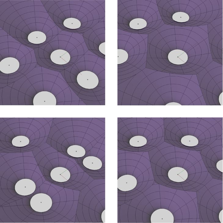
Figure 73: Four variations of the Responsive Acoustic Surface’s hyperboloid layout generated with Yeti. Slight changes in the hyperboloid position significantly alter the shape of the bricks.
In preparation for SmartGeometry 2011, the project team experimented with creating the Responsive Acoustic Surface in a variety of parametric modelling environments: Grasshopper, Digital Project, and Open Cascade. To best utilise the relative strengths of the various modelling environments, the hyperboloid brick was developed in a workflow that threaded the design between Grasshopper and Digital Project. Changes in this workflow took many minutes to propagate due to the time taken in exchanging data between software and the time taken in finding the intersections between hyperboloids. There was minimal feedback during this process and, as a result, the final relationship between hyperboloids was not obvious. The relationship would only become obvious when we built the hyperboloids, stacked them, and realised they did not quite fit together. The hyperboloids’ fit comes down to subtle nuances in the planarity of the intersections. Given the difficulty of calculating these intersections, the Responsive Acoustic Surface challenges all varieties of parametric model. By repeating the project with Yeti, the intention was to see if Yeti could remain interactive on such a challenging project and to see if the interactivity helped to understand the design better prior to construction.
Creating an array of hyperboloids was relatively straightforward in Yeti and not substantively different to distributing panels over the roof in Kilian’s second tutorial. The challenging part was intersecting the hyperboloids and then deciding which part of hyperboloids to keep. In a procedural paradigm this is easily expressed with an if-then-else structure:6 if part of the hyperboloid is past the intersection plane then delete the part else keep the part. The if-then-else structure is not yet included in Yeti primarily because adding it does not seem consistent with the rest of Yeti’s syntax. As a temporary workaround, the logic for deciding which part of the hyperboloid to keep was expressed procedurally in Yeti rather than expressed in Yeti’s YAML code. These challenges indicate some important functional differences between the dataflow paradigm of Yeti and the procedural paradigm of other textual languages.
The hyperboloid intersections were too arduous to calculate in real time with either Grasshopper or Yeti. The project could only be completed by pausing the interactivity, which effectively reverted Yeti back to the manual Edit-Compile-Run loop. Being able to revert to this non-interactive paradigm was useful to grind out the computationally taxing geometry of the hyperboloids, but reverting to a non-interactive paradigm also removes the primary impetus for creating Yeti in the first place. So while interactive textual programming is useful for straightforward calculations, on computationally difficult projects the Edit-Compile-Run loop may be inescapable, which possibly makes errors, like those contained in the original hyperboloid bricks, unavoidable.
SmartGeometry Redux Redux: Fabpod
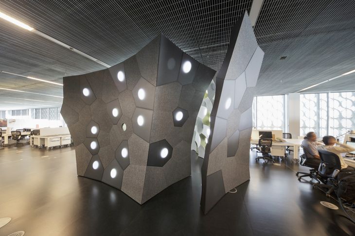
Figure 74: The entrance to the FabPod, situated within the RMIT DesignHub, Melbourne (March 2013).
A second iteration of the Responsive Acoustic Surface was developed as part of a design studio Nick Williams and John Cherrey ran at RMIT University in 2012 (with assistance from a research team led by Jane Burry and Mark Burry). The studio considered how the hyperboloid bricks of the Responsive Acoustic Surface could be adapted to acoustically diffuse sound in a meeting room. During the studio, the students designed a variety of meeting rooms for an open-plan office and later constructed one of the designs, which was dubbed the FabPod.
Based on analysis I had done for the Responsive Acoustic Surface, it was known that the hyperboloid bricks would only enclose spherical volumes.7 Previous research by Brady Peters and Tobias Olesen (2010) had suggested that the best acoustic performance would come from non-periodic tilings of the hyperboloids. For the FabPod, this was achieved by distributing the hyperboloids irregularly across spherical surfaces, and then trimming each hyperboloid where it intersected its neighbours. Doing so required finding the intersections between 180 hyperboloids, which was vastly more complicated than finding the intersections between the 29 regularly distributed hyperboloids of the Responsive Acoustic Surface. Further adding to the difficulty, the intersections were needed not only for creating the construction documentation at the end of the project, but also for generating models accurate enough to run the acoustic simulations used regularly throughout the project. Given how often these intersections were needed, I once again considered whether this process could be made interactive.
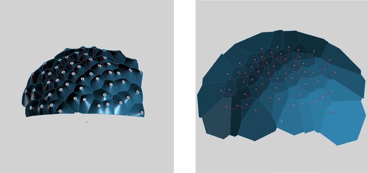
Figure 75: Left: An early study of hyperboloid intersections that I produced in January 2011 for the Responsive Acoustic Surface. The model proves that hyperboloids distributed on a spherical surface intersect with planar curves. Right: The intersections between hyperboloids also form a Voronoi pattern; shown is the output from the FabPod’s spherical Voronoi parametric model.
I began re-examining how the hyperboloid intersections were being generated. In previous parametric models (including the Yeti model) the hyperboloids were represented as NURBs surfaces and the intersections were calculated using numeric algorithms. While there are various numeric algorithms for finding the intersections between NURBs surfaces, in essence, all the algorithms involve iteratively moving a curve along one surface until the curve lies within a specified tolerance of the other surface (Patrikalakis 1993). Analytic equations are an alternative to using numeric algorithms. An analytic equation derives directly from a surface’s mathematical formula, which allows the intersection curve to be generated by directly solving the equation rather than spending computational resources doing iterative calculations. While analytic equations have some potential efficiencies, prior to this research, there was no existing analytic equation for calculating hyperboloid intersections.
Generating the analytic equation for the hyperboloid intersections was a multi-stage process. I first proved that the intersection planes between hyperboloids correspond with the pattern from a spherical Voronoi algorithm I developed (fig. 75). Lines between the Voronoi pattern and the sphere centre always correlate with points on the hyperboloid intersection curves. I derived an analytic algorithm to find these points by taking the formula for a hyperboloid:

And the formula for a line:
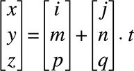
Substituting to eliminate x, y & z:

Which rearranges to give the value of t from the original line formula:

Using this analytic equation I developed a parametric model in Grasshopper for calculating the FabPod’s hyperboloid intersections. In the previous Grasshopper and Yeti models, calculating the intersections between 180 hyperboloids took approximately two and a half minutes (150,000ms). By utilising the analytic equation I was able to generate the same intersections in 250ms, which is one six-hundredth of the previous times and fast enough to feel interactive. With the intersections calculated so quickly, students in the workshop were able to make many small adjustments to their hyperboloid layouts while receiving real-time feedback about potential construction problems (edges that were too short, and hyperboloids that were too close or too far apart; fig. 76). All of these problems had to be eliminated in order for the FabPod to be constructible. I experimented with using hill-climbing and dynamic relaxation to remove the problems, but the search space was too disjointed to make this type of optimisation viable. Therefore the only way to ensure the FabPod’s constructability was to move each hyperboloid until the construction problems were resolved. If students had to wait two and a half minutes to see the outcome of every movement this would have been an unbearable task, which makes the real-time feedback supplied by the analytic algorithm an essential component in the FabPod’s viability.
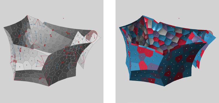
Figure 76: Left: The final spherical Voronoi pattern used in the FabPod. The blue and red lines provide feedback about the spacing of the hyperboloids and their constructability. Right: The final parametric model of the FabPod’s hyperboloid intersections. The colours correspond with construction materials.
Typically software engineers caution against spending large amounts of time optimising algorithms to reduce latency. Bertrand Meyer (1997, 9) warns, “extreme optimizations may make the software so specialized as to be unfit for change and reuse.” This is certainly true of my analytic algorithm, which is so highly tuned to calculating the FabPod’s hyperboloid intersections that it is of little use to any other project. On the other-hand, the generalised optimisations of Yeti are applicable in a wide range of circumstances, but not powerful enough to ensure the viability of the FabPod. In reducing parametric model latency there is a balance to find between extendability, correctness, reusability; a balance activated by the architect’s ability to explore multiple ways of generating parametric models.
7.7 – Conclusion
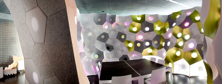
Figure 77: Panorama of FabPod (click for detail) in the final stages of construction at the RMIT DesignHub, Melbourne (February 2013).
Unlike at SmartGeometry 2011, I was not up at 3 a.m. writing code in the hours before the start of the FabPod workshop. Even more thankfully, there were no undetected errors lurking in the hyperboloid bricks and the project was constructed largely without incident. There are many reasons for this improvement: we knew the geometry better, we had a better construction system, the project was better managed, and we had better feedback while we were designing. Rather than blindly typing code and hoping (as we had done at SmartGeometry 2011) that the code output was correct, at the FabPod workshop we had immediate feedback regarding potential construction errors.
Immediate feedback has not always been possible for architects developing parametric models. Historically, geometric designers had to make a choice: either use an interactive visual editor, accepting the problems of scale this raises (see chap. 6); or forgo interactivity in favour of writing the code with text. Many people, including Ivan Sutherland (1963, 8), Bret Victor (2012), and Nigel Cross (2011, 11), have suggested that forgoing interactivity is undesirable since feedback is a vital part of the design process and one best delivered immediately. Their intuition is backed up by cognitive studies that show that novice programmers need progressive feedback (Green and Petre 1996, 8), and that designers suffer from change blindness when feedback is delayed (Erhan et al. 2009; Nasirova et al. 2011; see chap. 2.3). In other design disciplines, designers have access to a range of interactive textual programming environments yet, for architects, interaction and textual programming were incompatible prior to my research.
In this chapter I have demonstrated how Yeti’s novel method of interactive textual programming supports architects designing geometry. Unlike existing methods of interactive programming – which are ill equipped to accommodate the computational intensity of geometric calculations – Yeti enables the interactive creation of geometry by using a Directed Acyclic Graph (DAG) to manage code changes. In order to generate the DAG, Yeti is based on the relational markup language YAML, which is paradigmatically different to procedural programming languages but comparable in terms of construction time, code length, and functionality. Unlike many procedural programming environments, Yeti also incorporates a number of innovations software engineers have developed to make the Edit-Compile-Run loop feel more interactive, such as real-time error checking, autocompletion, and interactive debugging.
By using YAML to create a DAG, Yeti is able to reduce the latency between writing code and seeing the geometric results. On certain projects, like Kilian’s two roofs, the reduction in latency transforms a task that designers would typically do without any feedback into one designers can do with constant feedback. As a result, writing code and modifying code in Yeti become one and the same. On other projects, like the hyperboloids of the Responsive Acoustic Surface, Yeti does not reduce the latency sufficiency for interaction to occur and Yeti has to fall back on the Edit-Compile-Run loop. However, the FabPod demonstrates that designers can further reduce latency by trading off extendability, correctness, and reusability. In the case of the FabPod, this reduction in latency made a significant contribution towards identifying and then eliminating any construction problems. This indicates that qualities of a parametric model’s flexibility – like the model’s latency – can have a discernible impact on a project’s design. These qualities can themselves be designed through the composition of the parametric model or through the selection of the programming environment. Yeti demonstrates how knowledge from software engineering can offer a pathway towards more diverse programming environments that can be tuned for particular attributes of parametric modelling. Yeti is just one manifestation of this knowledge and there are many more possibilities that make programming environments for architects an obvious location for future development.
Thesis Navigation
- Return to table of contents
- Goto previous chapter
- Goto next chapter
- Download entire thesis as PDF (30mb)
Footnotes
1:The Responsive Acoustic Surface was built to test the hypothesis that hyperboloid geometry contributed to the diffuse sound of the interior of Antoni Gaudí’s Sagrada Família. For more information about the rationale for using hyperboloids in the Responsive Acoustic Surface and for more information about the surface’s acoustic properties, see Modelling Hyperboloid Sound Scattering by Jane Burry et al. (2011).
2:Interactive programming is primarily about changing code while it runs. Although this is useful for displaying code changes in real time, there are many other uses for interactive programming. A common use case is to update software that cannot be shut down (for example, life support systems and certain infrastructure systems). Instead of compiling and running a new instance of the software, software engineers can use interactive programming to apply code changes to the existing software while it runs.
3:Although the code continues to run when it is hot-swapped, there is no way of easily knowing how the hot-swapped code transforms the geometric model. Therefore, to update the model, the code must be rerun, which means hot-swapping in this context only saves compilation time and not running time.
4:By itself YAML is not a programming language since it describes data rather than computation (the concept of Turing completeness is therefore not applicable to YAML). But in Yeti this distinction is blurred because the YAML data describes the structure of a DAG, which in turn does computation. Some will say YAML is a programming language in this context, others will say it is still a data format.
5:It is remarkable to consider how much parametric modelling has changed in the seven years since Kilian’s tutorials, both in terms of the number of architects using parametric models and in terms of range of parametric modelling environments available to architects. While Kilian’s tutorials are just seven years old, in many respects they have an historic credence through which it is possible to track the development of parametric modelling.
6:The if-then-else structure is one of the three Böhm and Jacopini (1966) identified. They denote it with the symbol ∏. See chapter 6.2.
7:The bricks have a timber frame supporting the edges of the hyperboloids. Since it was only practical to build the frame from planar sections, the edges of the hyperboloids had to be planar as well. My analysis for the Responsive Acoustic Surface had demonstrated that adjoining hyperboloids only had planar edges in a limited range of circumstances: (1) the adjoining hyperboloids had to be of the same size, (2) the normals had to either be parallel or converge at a point equidistant from the hyperboloids. This can only occur if the hyperboloids are distributed on a planar surface with the normals parallel to the surface normal, or on a spherical surface with the normals pointing towards the centre. The FabPod uses spherical surfaces since they were shown to have better acoustic properties.
Bibliography
Brown, Tim. 2009. Change by Design: How Design Thinking Transforms Organizations and Inspires Innovation. New York: HarperCollins.
Burry, Jane, Daniel Davis, Brady Peters, Phil Ayres, John Klein, Alexander Peña de Leon, and Mark Burry. 2011. “Modelling Hyperboloid Sound Scattering: The challenge of simulating, fabricating and measuring.” In Computational Design Modeling: Proceedings of the Design Modeling Symposium Berlin 2011, edited by Christoph Gengnagel, Axel Kilian, Norbert Palz, and Fabian Scheurer, 89-96. Berlin: Springer-Verlag.
Card, Stuart, George Robertson, and Jock Mackinlay. 1991. “The Information Visualizer, an Information Workspace.” In Reaching Through Technology: Proceedings of the SIGCHI Conference on Human Factors in Computing Systems, 181–188. New Orleans: Association for Computing Machinery.
Celani, Gabriela, and Carlos Vaz. 2012. “CAD Scripting And Visual Programming Languages For Implementing Computational Design Concepts: A Comparison From A Pedagogical Point Of View.” International Journal of Architectural Computing 10 (1): 121–138.
Cross, Nigel. 2011. Design Thinking: Understanding How Designers Think and Work. Oxford: Berg.
Davis, Daniel, Jane Burry, and Mark Burry. 2012. “Yeti: Designing Geometric Tools with Interactive Programming.” In Meaning, Matter, Making: Proceedings of the 7th International Workshop on the Design and Semantics of Form and Movement, edited by Lin-Lin Chen, Tom Djajadiningrat, Loe Feijs, Simon Fraser, Steven Kyffin, and Dagmar Steffen, 196–202. Wellington, New Zealand: Victoria University of Wellington.
Erhan, Halil, Robert Woodbury, and Nahal Salmasi. 2009. “Visual Sensitivity Analysis of Parametric Design Models: Improving Agility in Design.” In Joining Languages, Cultures and Visions: Proceedings of the 13th International Conference on Computer Aided Architectural Design Futures, edited by Temy Tidafi and Tomás Dorta, 815–829. Montreal: Les Presses de l'Université de Montréal.
Evans, Clark. 2011. “The Official YAML Web Site.” Last modified 20 November. http://www.yaml.org/.
Green, Thomas, and Marian Petre. 1996. “Usability Analysis of Visual Programming Environments: A ‘Cognitive Dimensions’ Framework.” Journal of Visual Languages & Computing 7 (2): 131-174.
Janssen, Patrick, and Kian Chen. 2011. “Visual Dataflow Modeling : A Comparison of Three Systems.” In Designing Together: Proceedings of the 14th International Conference on Computer Aided Architectural Design Futures, edited by Pierre Leclercq, Ann Heylighen, and Geneviève Martin, 801–816. Liège: Les Éditions de l’Université de Liège.
Jenett, Florian. 2012. “Simplelivecoding Source.” Github. Last modified 13 November. https://github.com/fjenett/simplelivecoding.
Lawson, Bryan. 2005. How Designers Think: The Design Process Demystified. Fourth edition. Oxford: Elsevier. First published 1980.
Leitão, António, Luís Santos, and José Lopes. 2012. “Programming Languages for Generative Design: A Comparative Study.” International Journal of Architectural Computing 10 (1): 139–162.
McCartney, James. 2002. “Rethinking the Computer Music Language: Super Collider.” Computer Music Journal 26 (4): 61–68.
Meyer, Bertrand. 1997. Object-Oriented Software Construction. Second edition. Upper Saddle River: Prentice Hall.
Miller, Robert. 1968. “Response Time in Man-Computer Conversational Transactions.” In Proceedings of the AFIPS Fall Joint Computer Conference, 267–277. Washington, DC: Thompson.
Nasirova, Diliara, Halil Erhan, Andy Huang, Robert Woodbury, and Bernhard Riecke. 2011. “Change Detection in 3D Parametric Systems: Human-Centered Interfaces for Change Visualization.” In Designing Together: Proceedings of the 14th International Conference on Computer Aided Architectural Design Futures, edited by Pierre Leclercq, Ann Heylighen, and Geneviève Martin, 751–764. Liège: Les Éditions de l’Université de Liège.
Patrikalakis, Nicholas. 1993. “Surface-to-Surface Intersections.” Computer Graphics and Applications 13 (1): 89–95.
Peters, Brady, and Tobias Olesen. 2010. “Integrating Sound Scattering Measurements in the Design of Complex Architectural Surfaces.” In Future Cities: 28th eCAADe Conference Proceedings, 481–491. Zurich: ETH Zurich.
Schön, Donald. 1983. The Reflective Practitioner: How Professionals Think in Action. London: Maurice Temple Smith.
Smith, Rick. 2007. “Technical Notes From Experiences and Studies in Using Parametric and BIM Architectural Software.” Published 4 March. http://www.vbtllc.com/images/VBTTechnicalNotes.pdf.
Sorensen, Andrew, and Henry Gardner. 2010. “Programming With Time: Cyber-physical Programming with Impromptu.” In Onward! Proceedings of the Association for Computing Machinery International Conference on Object Oriented Programming Systems Languages and Applications, 822–834. Tahoe: Association for Computing Machinery.
Sorensen, Andrew. 2005. “Impromptu : An Interactive Programming Environment for Composition and Performance.” In Generate and Test: Proceedings of the Australasian Computer Music Conference 2005, 149-154. Brisbane: ACMA.
Sutherland, Ivan. 1963. “Sketchpad: A Man-Machine Graphical Communication System.” PhD dissertation, Massachusetts Institute of Technology.
Victor, Bret. 2012. “Inventing on Principle.” Presentation at Turing Complete: Canadian University Software Engineering Conference, Montreal, 20 January. Digital video of presentation, accessed 19 November 2012. http://vimeo.com/36579366.
Wang, Ge, and Perry Cook. 2004. “On-the-fly Programming : Using Code as an Expressive Musical Instrument.” In Proceeding of the 2004 International Conference on New Interfaces for Musical Expression, 138–143.
Woodbury, Robert, Robert Aish, and Axel Kilian. 2007. “Some Patterns for Parametric Modeling.” In Expanding Bodies: 27th Annual Conference of the Association for Computer Aided Design in Architecture, edited by Brian Lilley and Philip Beesley, 222–229. Halifax, Nova Scotia: Dalhousie University.
Woodbury, Robert. 2010. Elements of Parametric Design. Abingdon: Routledge.
Illustration Credits
- Figure 57 – Photograph by Daniel Davis, March 2011
- Figure 58 – Photograph by Daniel Davis, March 2011
- Figure 59 – Photograph by Daniel Davis, March 2011
- Figure 60 – Daniel Davis
- Figure 61 – Bret Victor 2012
- Figure 62 – Daniel Davis
- Figure 63 – Daniel Davis
- Figure 64 – Daniel Davis
- Figure 65 – Daniel Davis
- Figure 66 – Daniel Davis
- Figure 67 – Daniel Davis
- Figure 68 – Daniel Davis
- Figure 69 – Daniel Davis
- Figure 70 – Daniel Davis
- Figure 71 – Daniel Davis
- Figure 72 – Daniel Davis
- Figure 73 – Daniel Davis
- Figure 74 – Photograph by John Gollings, March 2013
- Figure 75 – Daniel Davis
- Figure 76 – Daniel Davis
- Figure 77 – Daniel Davis
